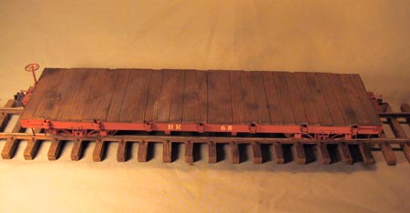
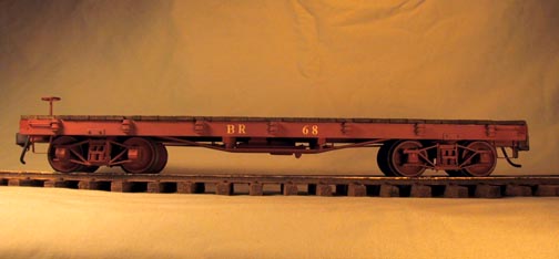
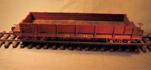
In 1992, BIG RIVER RAILROAD needed some rolling stock, so the shop was directed to construct some flat cars. These could be modified to become low side gondolas, or tankcars. The underbody construction is the same for boxcars, reefers, and stockcars. This is a description of the process.
Making multiples drastically reduced the time required to make
each piece, since the set up time was spread over all the pieces.
Consider making more than one car at a time. Plans were drawn
up inspired by the Southern Pacific prototype 30' flat car (UNDERFRAME DRAWINGS). This
same construction technique was used on many narrow gauge railroads,
with the exception that the SP didn't use turnbuckles on the truss
rods. All the dimensions in this article are based on a scale
of 1/2" = 1 foot.
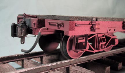
At this point a decision needs to be made about couplers. I use a body mounted coupler, which is a modified version of a Precision Scale coupler with a working lift pin, so the Draft Beam dimensions given are to suit that coupler installation. The details of this area will vary depending on your choice of coupler. If a Kadee box is used the Draft Beams should be cut shorter to fit.
Another basic decision is the method of mounting the trucks. I
use a 6-32 screw with a shoulder spacer and nut. A round head
wood screw, or a sheet metal screw, could be used as well.
Once the plans were finalized in detail, a cutting list was made
giving quantities and dimensions of all the stock required (CUTTING LIST). I used Western Pine
since it machines very well and is easily available. The stock
sizes were ripped on a table saw and cut to length on a radial
arm saw. A cutting stop clamped to the fence of the radial arm
saw allowed easy duplication of a desired length. Using a wood
plane clamped in the bench vise, all the stock is surfaced on
four sides before being cut to length on the radial arm saw. This
produced a satin smooth surface with crisp corners in much less
time than trying to sand everything.
Spacers are used to aid the assembly of the Rails to the End Beams. I use ACC with an accelerator on all my joints. Put the medium viscosity glue on one piece to be joined and spray the accelerator on the other. Hold the pieces together for a few seconds and the joint is set. A good wood glue, like Titebond II, can be used as well, but the assembly time is a little slower. First glue the two Center Rails together using pieces of the stock for Coupler and Truck Screws. The length of these pieces will vary depending on the choice of coupler and truck mounting system. Glue this assembly and two more Center Rails to each End Beam. Check that the Rails are square to the End Beams. The Side Rails need to be notched to fit over the End Beams. By fitting each Side Beam the joint can be tight. Again check that the entire frame is square.
Bottom of a finished car.
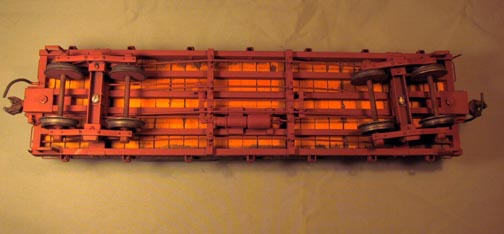
After the basic frame is assembled, the Bolsters are trimmed to fit and installed. The Needle Beams are notched to fit and installed in the proper location. Finally, the Buffer Blocks and the Draft Beams are installed. Bevel the inside ends of the Draft Beams. Cut the Truss Rod Support Blocks to fit and install them along the centerline of the Bolster. Reinforce all the glue joints with a fillet of ACC on the inside corners. Sand the entire top of the frame to insure a flat surface for the decking.
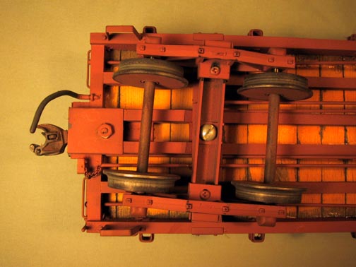
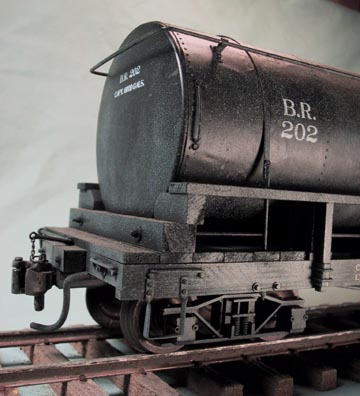
Determine which style of queen posts you want to use and draw a full size drawing of a truss rod. I use 1/16" diameter brazing rod as my stock. This is readily available at any welding supply house. This rod scales to 1-1/2" and can be threaded for an 0-80 nut. Cut the rods to length, thread the ends, and bend them to shape. Mark and drill the End Beams for the truss rods, and mark and drill the Needle Beams for the queen posts.
Install the truss rods using 2-56 washers on the outer truss rods. I decided to model a buffer plate for the two inner truss rods, using 0.020" copper sheet. Copper sheet can be found at any sheet metal shop where it is used for high quality roof flashing. These rods are installed using 0-80 washers. If you choose not to model this plate, use 2-56 washers like the outside truss rods. The coupler screw is 4-40 x 5/8" threaded through from the top. The head is countersunk and ACCed in place. The box lid is .020" copper, folded at the edges, with two 1/16" rods soldered in for reinforcement. The rods fit into holes in the Draft Beam and provide additional strength to the coupler installation. A nut secures the lid.
Stake pockets can be purchased, but I make my own. I use 0.020" copper sheet for material. I cut strips 11/32" wide by any convenient length. Anneal the strips by heating them red hot and allowing them to slowly cool. Scribe lines to locate the mounting holes. I made a mating punch set which would bend the strip into the "U" shape. I then punch a whole series of these "U" shapes in each annealed strip. I use #18 ga copper wire (0.040" = scale 1") to mount the stake pockets, so I drill 0.046" holes on either side of each "U" pocket, while they are still all in one strip. Then cut the individual pockets apart and clean up the edges with a file. Mark and drill the Side Rails for the mounting wires. Bend them over on the inside and secure with ACC.
Using 0.020" copper sheet, fabricate Bolster Tie Rod Plates. These tie rods helped transfer the load of the car from the outside rails to the center king post of the truck. The rod ends are modeled using #19 ga wire brads. These same brads are used to model a simplified grab iron bolt. The grab iron is #18 ga copper wire bent in a "U" and mounted in holes drilled in the Side Rails and End Beams. The grab irons are installed first and then the holes for the brads are drilled next to the grab irons. The result looks fine from a distance. Identical grabs can be formed using a jig made of wood or plastic. Drill a hole the correct distance from one edge. Bend one leg of the grab iron, insert it in the hole, and use the edge of the jig as a guide to hold the wire for bending the second leg. Drill and mount all the grab irons. Trim the brads and wire flush with the inside of the frame members and apply ACC to secure everything. Notice that all the grabs are above the "bolts" except for the left hand one on each end. This allows clearance for the lift bar.
There are several fine "K" brakes on the market. Install the brake cylinder and all the rigging. The cylinder base supports are 1/16" thick pine. The parts of the rigging are fabricated from #18 ga copper wire, with 0.020" copper sheet for the clevises, which are soldered to the rigging parts. The brake levers are 0.030" styrene, and the lever support straps are #18 ga wire. The clevises are ACCed to the levers.
The corner steps are 1/8" x 0.020" copper bent to shape and drilled for #19 brads, which secure the step to the Side Rails. The brake wheel support is fabricated from 0.020" copper sheet and 1/16" dia. brass tube. This is designed to receive a Bachmann brake wheel. The bracket is secured to the End Beam using #18 ga wire, similar to the stake pocket mounting system. A short length of chain is wrapped around the brake wheel shaft and connect to the loop at the end of the brake rigging. There are good castings on the market as well.
Part of the goal of the BIG RIVER is to switch cars. The couplers I use have working lift pins, so working lift bars are necessary. The bars are 1/16" rod, bent to the correct shape. The "B" end has to jog around the brake wheel shaft. Eyebolts are bent from 0.040" wire and soldered for strength. The eye is then drilled out. The coupler end of the lift bar has a .040" wire ring soldered on to attach a piece of chain. Another ring connects the chain to the top of the lift pin. The Eyebolts are pressed into holes in the End Beam. An easy was to make lots of rings of various sizes is to wrap the wire around a drill of the desired size. Make 20 or so wraps and then slide the coil off the drill. Use a fine jewelers saw to cut the coil along its length. This produces individual rings. I make a bunch anytime I need one, then I have them for future projects.
I used #14 ga solid electrical wire for brake hoses. This is the correct diameter and will hold a shape easily. The end of the wire is bent and inserted in a hole in the End Beam. For further strength, a loop of 0.040" wire is installed. Everything is held with ACC.
The basic car is now ready to be painted. Since these cars are so big, I have started using exterior latex paint. After several tries I have found a color which looks like sun bleached Red Oxide, which was a very common color for railroads, since it was cheap. I spray painted the flat car frames without couplers, and the truck side frames and wheels, after masking the treads and axle ends. I "rusted" the couplers and lubricated them with graphite until they worked smoothly. The trucks were then lubricated, assembled and installed. I am using metal wheels in Bachmann side frames, and find that I don't need to add any extra weight.
The deck is the last part to add. The boards are cut back above the stake pockets and over the side grab irons. The individual boards are distressed with a hacksaw blade and whatever other implement of destruction comes to mind. I then tape the boards together as they will go on the car and add gouges and scrapes across several boards at once. This entire assembly is then stained dark with a mixture of very dirt thinner and splotches of paint rubbed in with more thinner. Weathering is where the art of illusion comes into model making. Experiment. It's virtually impossible to really ruin something. The boards are then glued down to the frame. The entire car gets some weathering for dirt and grime. I use custom dry transfers or decals for lettering.
On two cars, I added low board sides, which are removable. The upper edges are distressed and rasped to shape. The grab irons are made the same way as on the frame. The post bolts are more #19 brads. They are painted a less faded color as if the board sides were added later.
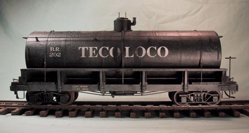
The sixth car had been designed to be a tank car. It had only 6 pockets on each side rather than 7, and the queen posts were longer. The tank was fabricated from 2" ABS sewer pipe with Plexiglas ends. The dome is 3/4" PVC pipe with a Plexiglas top. I wrapped various areas with 0.010" styrene, dimpled for rivets. This simulated a five section tank, typical of the era. The hand rail is 0.040" wire. There are two longitudinal truss rods to connect the end mounting blocks. The five tie down straps have 1/16" rods soldered on which are threaded to allow the tank to be bolted to the frame.
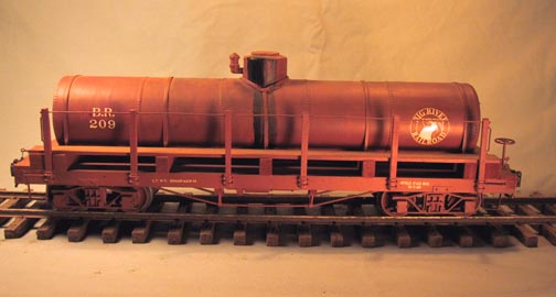
The total investment in each flat car came to 8 1/2 hours and $8.00. Each gondola took 10 1/2 hours and $8.00. The tank car took 17 hours and $10.00. These material cost do not include trucks or couplers.
In the summer of 2000, I built another round of freight cars. This time it was a fleet of 6 tank cars and 7 boxcars. The underframe construction was the same as the above article.
The tank cars were modeled after the Pacific Coast tank cars that ran in central California. Whereas the first tank car I built was essentially a tank on a flat car, these are more a tank on a frame. The tanks are a larger diameter, but are constructed the same way. I used ABS drain pipe for the basic tank, wrapped with 0.010" styrene sheet which was dimpled for rivets. I applied the styrene to the ABS with contact cement. This was a mistake in retrospect, since the contact cement solvent reacted with the styrene, forming bumps and blisters. By the time this became apparent, I was too far along in the rest of the construction to consider throwing it all away. I would use either ACC or MEK in the future.
The tank ends are 1/4" acrylic sheet, turned in a lathe. They are glued to the ABS pipe before the styrene wrapper is applied. The tank dome is PVC pipe, with an turned acrylic top. The hand rails are 1/16" dia. rod mounted in copper sheet stanchions which are nailed to the tank with Atlas track nails. This makes for a very durable, yet delicate, railing. I had Rick Blanchard make me custom decals for these cars. TECOLOCO stands for Tecolote Oil Company, and is inspired by the CONOCO cars.
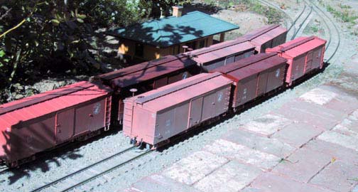
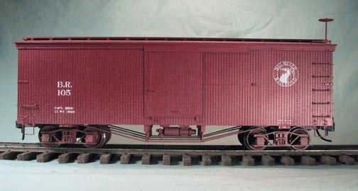
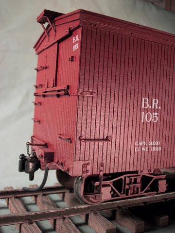
I also built a set of boxcars. I am modeling a narrow gauge railroad in the late 1920's, when many other narrow gauge roads had gone under or been converted to standard gauge. Consequently, I imagine that the Big River has bought up old car bodies from other roads. Of the 7 boxcars I built, 3 are SP prototype, 2 are from the Pacific Coast with corrugated roofing, and the other two are Pacific Coast cars that came from other roads before them. The four styles are slightly different lengths, widths and heights, giving a feel of variety to the cut of cars. I painted them different shades of red to represent a very faded, a slightly faded, and new from the shop appearance.
The basic underframe is as described above, except that the outer side rails are the same dimension as the inner rails. This is because the structure of the box car side stiffens the frame enough that the larger beam isn't needed. These are all 30' cars. On longer cars, the side beams are deeper.
I used mahogany door skin material for the basic body structure. A piece was glued to the underframe for the floor. Pine blocks, 3/4" thick, were glued to the ends to provide support and enough body for grab irons. Extra pieces of pine were glued in to provide support for grab irons along the sides. The roof was another piece of pine, beveled on each side for the proper roof slant. Door skin material was glued on for the sides. I decided to not make the boxcars doors open, which simplified construction. The sides, ends, and roof were sheeted with 1/16" scribed basswood siding. On two of the cars, the roof was made with my galvanized corrugated steel.
The end and side doors were made from scribed basswood, and the hardware was made from bits of wood and wire. Atlas track nails were used for bolts in various places. The roof walks are basswood stock. I used commercial brake wheels, brake staff hardware, and "K" brake cylinders. On these cars I have not added the entire brake rigging. I'm getting lazier as time goes by, and when you are standing beside the car, you can really see the underbody detail.
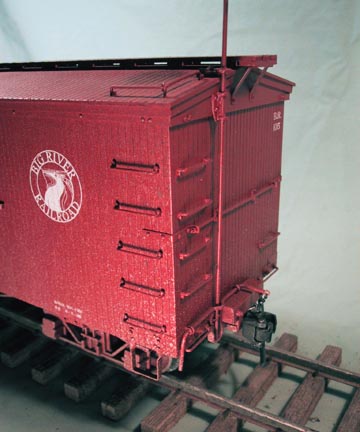
Here is the whole fleet of 7 boxcars. The variation in the paint color gives a sense of history to the cars. The more faded colors were weathered more heavily as well.